Temperature measurement using a NTC thermistor and an AVR microcontroller
Calculating the temperature
Schemes of connection
Connecting of thermistor
Connecting to ADC of MCU ATmega
Online table calculation
Example of usage
Author: Pogrebnyak Dmitry
Russia, Samara, 2013.
Внимание. Сей опус является неубедительной моей попыткой перевести собственное творчество на ломанный английский язык. Поэтому, если вам русский язык кажется чем-то родным и близким, то прочтите, пожалуйста, оригинал этого манускрипта на родном языке автора. Впрочем, если вы при этом знакомы с языком, претерпевшем много боли ниже по тексту, и обладаете крепкими нервами и здоровым чувством юмора, то, как говорится, ю а вэлкам.
Note. This is a weak translation of an article originally written in Russian. So, if you famous with Russian language, it is preferred to read it in the original language.
One of methods to measure temperature is to use a thermal resistor (or a thermistor for short). It has significant value of the thermal coefficient, i.e. changing of resistance with changing of temperature (at level of 2-10% per Kelvin).
There are two types of thermistors – Positive Temperature Coefficient (PTC) which increases their resistance when temperature is growing up; and Negative Temperature Coefficient (NTC) which decreases resistance when temperature is growing. This article describes usage of a NTC only in link with an AVR MCU for purposes of temperature measurement.
NTC thermistor characteristics
Thermistors have a lot of parameters that characterize them, such as: maximum allowed current, resistance tolerance, resistance at particular temperature (usually 25°С). One of them is a coefficient of temperature sensitivity or the B parameter. This parameter is calculated, when measuring two resistance values for two different temperatures. In most cases it is 25°С and 100°С. Usually, temperatures that was used to calculate B is printed after the B letter, for example: B25/100. The B parameter measured in Kelvins and can be calculated, using the formula:
R1 and R2 - the values of resistance for temperatures T1 and T2 respectively, expressed in Kelvins.
There are the reverse formulas:
Calculating the temperature
Parameters of thermistors have high level of non-linearity. The B parameter has different values, when measurement based on different temperatures. Two different models of thermistors with same B25/100 value could change their resistance in different ways over a temperature range.
Thus formula [3] can be used only for a rough estimation of temperature. In addition, this formula requires heavy calculation, which requires much of CPU time. Since the CPU of the MC usually has no floating point math support, these calculations are not applicable.
A better way is to store a table in the memory, whose cells will contain precalculated ADC values, corresponding to temperatures.
For memory economy it is possible to store ADC values only for several temperature points (given with some step), then to find it using binary search and to calculate resulting temperature, using linear interpolation.
To measure ambient temperature in range from -30°С to +70°С with accuracy up to 0.3°С, it is require to store 20 values (with step of 5°С). If every value will fit into 16 bits, it will require only 40 bytes of the flash-memory – that is much less, than memory required to store floating math routines.
Decreasing table step down to 2°С, it is possible to take accuracy at level of 0.1°С on wide measurement range.
Vendors of thermistors usually give tables of R/T characteristics, which show how resistance changed over temperature. For example, Siemens-EPCOS gives those tables with step of 5°С. To calculate intermediate values, it is possible to interpolate them with high accuracy, using formulas [1] and [2].
Schemes of connection
Connecting of thermistor
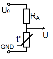 |
| Scheme A |
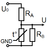 |
| Scheme B |
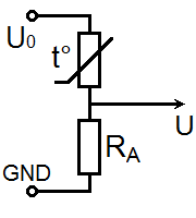 |
| Scheme C |
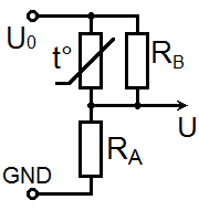 |
| Scheme D |
The simplest way to connect thermistor to a MCU (or an ADC IC) is Scheme A.
To minimize measurement error, the RA value should be close to thermistor resistance value in the measurement range – that makes ADC values changing closer to linear, and consequently, allows to minimize error while linear interpolation.
When selecting values of thermistor resistance and RA, it is should be taking into account, that current that flow thru the thermistor, will provoke its heating, and, as consequence, distortion of the measured value. It is desirable, than dissipated power on thermistor never excess 1mW. Thus, if input voltage U0 = 5V, then values of RA and thermistor resistance at measured range should be at least 10 kiloOhms each.
Scheme B is used to minimize power dissipated on thermistor.
Schemes C and D – is reverse for A and B. They are to use, if required to measure low temperatures, when ADC referent voltage (Uref) is lower than U0.
Connecting to ADC of MCU ATmega
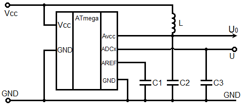 |
| Connection of ATmega ADC |
To minimize a noise, inducted by digital lines, MCUs ATmega use separate power supply pins for the ADC module. The datasheet recommends to connect these pins through a filter: the inductance L = 10µH, and the capacitor C2 = 0.1µF.
The ADC of the MCU can use as referent voltage either external voltage, connected to AREF pin, or internal 2.56V or 1.1V (depend on MCU model), or use AVCC supply voltage as referent value. When internal or AVCC voltage is used, an external capacitor must be connected between the analog ground and the AREF pin. The datasheet gives no exact recommendation for choosing this capacitance. I recommend to use a ceramic capacitor 0.1µF or more.
To minimize a noise, I recommend to use same filtered voltage, which is used for AVCC line, to supply thermistor scheme, and to use same AVCC as referent voltage.
Additionally, to suprres noises in wires, the capacitor C3 (1-100nF) could be installed.
Should be taken into account, that, besides of the ADC, the AVCC input used to supply digital levels on some pins (usually this is the same pins, where ADC inputs is located). Usage of those pins for digital input/output and connecting a load to it can produce an additional noise on the ADC.
To minimize measured ADC noises, and increase accuracy, I recommend to perform several consequent measurements, and to sum their results. ATmegas have 10-bit ADC. Sum of 64 measurements still be in range of 16-bit integer, thus not require additional memory to store table of values.
When making more measurements, it is possible to keep it in range of 16 bits, by dividing or shifting result.
Online table calculation
Here I brought for your comfort the online script for ADC values table calculation.
Calculation is performed by:
- Two values of temperature and corresponded to them values of thermistor resistance;
- One pair of temperature/resistance and B coefficient;
- Entered list of R/R1 values given with some step;
- One of preloaded R/T characteristics.
Now there are preloaded R/T characteristics for Siemens/EPCOS thermistors. Please, select one, which corresponds to yours. Preloaded characteristics are given with step of 5°С. When selecting the grid step less than 5°С, intermediate values are calculated using the formulas [1] and [2].
When the table is renewed, the source code under it is updating automatically.
Note! Due to high non-linearity of thermistor parameters, calculations based on two values are rough and then calculated value of temperature can be significant different from actual one for high and low temperature measurements.
To know what R/T characteristics correspond to your thermistor, please refer to vendor datasheets.
Here the table of commonly used thermistors Siemens/EPCOS is given. Press to an R/T characteristic code to load it into the calculation form below.
| Code | Resistance when 25°С, kOhm | R/T characteristic | B25/100, К | |
| B57891S, though-hole 4.5mm (1.8’’) (datasheet, pdf) | ||||
| B57891S0222+008 | 2,2 | 1008 | 3560 | |
| B57891S0502+008 | 5 | 2003 | 3980 | |
| B57891S0103+008 | 10 | 4901 | 3950 | |
| B57891S0203+008 | 20 | 2904 | 4300 | |
| B57891S0104+008 | 100 | 4003 | 4450 | |
B57891M, through-hole 3.5mm (1.4’’) (datasheet, pdf) | ||||
| B57891M0102+000 | 1 | 1009 | 3930 | |
| B57891M0152+000 | 1,5 | 1008 | 3560 | |
| B57891M0222+000 | 2,2 | 1013 | 3900 | |
| B57891M0332+000 | 3,3 | 2003 | 3980 | |
| B57891M0472+000 | 4,7 | 2003 | 3980 | |
| B57891M0682+000 | 6,8 | 2003 | 3980 | |
| B57891M0103+000 | 10 | 4901 | 3950 | |
| B57891M0153+000 | 15 | 2004 | 4100 | |
| B57891M0223+000 | 22 | 2904 | 4300 | |
| B57891M0333+000 | 33 | 2904 | 4300 | |
| B57891M0473+000 | 47 | 4012 | 4355 | |
| B57891M0683+000 | 68 | 4012 | 4355 | |
| B57891M0104+000 | 100 | 4003 | 4450 | |
| B57891M0154+000 | 150 | 2005 | 4600 | |
| B57891M0224+000 | 220 | 2005 | 4600 | |
| B57891M0334+000 | 330 | 2007 | 4830 | |
| B57891M0474+000 | 470 | 2006 | 5000 | |
B57164K, through-hole 5.5mm (2.2’’) (datasheet, pdf) | ||||
| B57164K0471+000 | 0,47 | 1306 | 3450 | |
| B57164K0681+000 | 0,68 | 1307 | 3560 | |
| B57164K0102+000 | 1 | 1011 | 3730 | |
| B57164K0152+000 | 1,5 | 1013 | 3900 | |
| B57164K0222+000 | 2,2 | 1013 | 3900 | |
| B57164K0332+000 | 3,3 | 4001 | 3950 | |
| B57164K0472+000 | 4,7 | 4001 | 3950 | |
| B57164K0682+000 | 6,8 | 2903 | 4200 | |
| B57164K0103+000 | 10 | 2904 | 4300 | |
| B57164K0153+000 | 15 | 1014 | 4250 | |
| B57164K0223+000 | 22 | 1012 | 4300 | |
| B57164K0333+000 | 33 | 1012 | 4300 | |
| B57164K0473+000 | 47 | 4003 | 4450 | |
| B57164K0683+000 | 68 | 2005 | 4600 | |
| B57164K0104+000 | 100 | 2005 | 4600 | |
| B57164K0154+000 | 150 | 2005 | 4600 | |
| B57164K0224+000 | 220 | 2007 | 4830 | |
| B57164K0334+000 | 330 | 2006 | 5000 | |
| B57164K0474+000 | 470 | 2006 | 5000 | |
B57540G, through-hole, glass "water drop" 0.8mm (0.3’’) (datasheet, pdf) | ||||
| B57540G0502+000, +002 | 5 | 8402 | 3497 | |
| B57540G1103+000, +002 | 10 | 8307 | 3492 | |
| B57540G1103+005, +007 | 10 | 7003 | 3625 | |
| B57540G0203+000, +002 | 20 | 8415 | 4006 | |
| B57540G1303+005, +007 | 30 | 7002 | 3988 | |
| B57540G0503+000, +002 | 50 | 8403 | 4006 | |
| B57540G1104+000, +002 | 100 | 8304 | 4092 | |
| B57540G0234+000, +002 | 230 | 8405 | 4264 | |
| B57540G0145+000, +002 | 1400 | 8406 | 4581 | |
B57551G, through-hole, glass "water drop" 1.8mm (0.7’’) (datasheet, pdf) | ||||
| B57551G0202+000, +002 | 2 | 8401 | 3436 | |
| B57551G1103+000, +002 | 10 | 8307 | 3492 | |
| B57551G1103+005, +007 | 10 | 7003 | 3625 | |
| B57551G1303+005, +007 | 30 | 7002 | 3988 | |
| B57551G1104+000, +002 | 100 | 8304 | 4092 | |
B57621С5, SMD 1206 3.2х1.6mm (datasheet, pdf) | ||||
| B57621C5102+062 | 1,0 | 3206 | 3450 | |
| B57621C5472+062 | 4,7 | 1309 | 3520 | |
| B57621C5103+062 | 10 | 1010 | 3530 | |
| B57621C5153+062 | 15 | 1008 | 3560 | |
B57621С0, SMD 1206 3.2х1.6мм (datasheet, pdf) | ||||
| B57621C0222+062 | 2,2 | 1308 | 3060 | |
| B57621C0332+062 | 3,3 | 1309 | 3520 | |
| B57621C0472+062 | 4,7 | 1309 | 3520 | |
| B57621C0103+062 | 10 | 1010 | 3530 | |
| B57621C0153+062 | 15 | 1008 | 3560 | |
| B57621C0223+062 | 22 | 1008 | 3560 | |
| B57621C0333+062 | 33 | 2003 | 3980 | |
| B57621C0473+062 | 47 | 2001 | 3920 | |
| B57621C0683+062 | 68 | 2001 | 3920 | |
| B57621C0104+062 | 100 | 4901 | 3950 | |
| B57621C0154+162 | 150 | 2903 | 4200 | |
| B57621C0224+062 | 220 | 2903 | 4200 | |
| B57621C0334+062 | 330 | 1014 | 4250 | |
| B57621C0474+062 | 470 | 1014 | 4250 | |
B57703M, probe 10mm, with mounting plate 8.5x3.7mm with hole(datasheet, pdf) | ||||
| B57703M0502G040 | 5 | 8016 | 3988 | |
| B57703M0103G040 | 10 | 8016 | 3988 | |
| B57703M0303G040 | 30 | 8018 | 3964 | |
Form for online calculating of ADC values
| Table data |
*Due to non-linearity of thermistor parameters, calculations based on two points are rough, and, when measuring high or low temperatures, calculated value will significantly differ from real one.
For precise measuring in wide temperature range, please, select one of preloaded R/T characteristics, which corresponds to your NTC-thermistor, in drop-down list above.
|
| T1 | °С |
| R1, resistance when T1 | kiloOhm |
| T2 | °С |
| R2, resistance when T2 | kiloOhm |
| Data for table:R/R1 starting from T2, with selected grid step. Use comma to separate values. | |
| BT1/T2 | K |
| Scheme of thermistor connection | |
| Resistor RA value | kiloOhm |
| Resistor RB value | kiloOhm |
| ADC resolution | |
| Multiplier for ADC result | |
| U0, source voltage | В |
| Uref, ADC referent voltage | В |
| Calculate from | °С to °С |
| Grid step | |
| T,°С | R/R1 | R,kiloOhm | U,V | I,µA | P,mW | U/Uref | ADC | E,°С |
|---|
Explanation of table fields:
Bold values of R/R1 and R columns are taken from preloaded array, or entered values. Non-bold values are obtained by calculations, using formulas.
ADC – the rounded value that will be taken from ADC output, with respect to multiplier. Values that fallen out of ADC range, are not displayed here.
I,µA - current in whole circuit.
P,mW - power, dissipating on thermistor.
E – heuristic estimation of a measured value error, when using the linear interpolation, taking into account a limited ADC accuracy. It enables to find parameters and scheme to minimize an error in a range of measured temperatures. This estimation does not taking into account an ADC noise, and a heating of thermistor due to power dissipation on it.
The error value could be lowered when selecting a lower grid step, selecting the ADC of higher resolution, averaging of many measurements, and by selection of resistors values.
Code, corresponding to table
#include <avr/io.h>
#include <avr/pgmspace.h>

// Value when sum of ADC values is more than first value in table
#define TEMPERATURE_UNDER 0
// Value when sum of ADC values is less than last value in table
#define TEMPERATURE_OVER 0
// Value corresponds to first entry in table
#define TEMPERATURE_TABLE_START 0
// Table step
#define TEMPERATURE_TABLE_STEP 50

// Type of each table item. If sum fits into 16 bits - uint16_t, else - uint32_t
typedef uint16_t temperature_table_entry_type;
// Type of table index. If table has more than 255 items, then uint16_t, else - uint8_t
typedef uint8_t temperature_table_index_type;
// Access method to table entry. Should correspond to temperature_table_entry_type
#define TEMPERATURE_TABLE_READ(i) pgm_read_word(&termo_table[i])

/* Table of ADC sum value, corresponding to temperature. Starting from higher value to lower.
   Next parameters had been used to build table:
*/
const temperature_table_entry_type termo_table[] PROGMEM = {
  0 // Press "Build table" button on form above to fill this array
};

// This function is calculating temperature in tenth of degree of Celsius
// depending on ADC sum value as input parameter.
int16_t calc_temperature(temperature_table_entry_type adcsum) {
  temperature_table_index_type l = 0;
  temperature_table_index_type r = (sizeof(termo_table) / sizeof(termo_table[0])) - 1;
  temperature_table_entry_type thigh = TEMPERATURE_TABLE_READ(r);

  // Checking for bound values
  if (adcsum <= thigh) {
    #ifdef TEMPERATURE_UNDER
      if (adcsum < thigh)
        return TEMPERATURE_UNDER;
    #endif
    return TEMPERATURE_TABLE_STEP * r + TEMPERATURE_TABLE_START;
  }
  temperature_table_entry_type tlow = TEMPERATURE_TABLE_READ(0);
  if (adcsum >= tlow) {
    #ifdef TEMPERATURE_OVER
      if (adcsum > tlow)
        return TEMPERATURE_OVER;
    #endif
    return TEMPERATURE_TABLE_START;
  }

  // Table lookup using binary search
  while ((r - l) > 1) {
    temperature_table_index_type m = (l + r) >> 1;
    temperature_table_entry_type mid = TEMPERATURE_TABLE_READ(m);
    if (adcsum > mid) {
      r = m;
    } else {
      l = m;
    }
  }
  temperature_table_entry_type vl = TEMPERATURE_TABLE_READ(l);
  if (adcsum >= vl) {
    return l * TEMPERATURE_TABLE_STEP + TEMPERATURE_TABLE_START;
  }
  temperature_table_entry_type vr = TEMPERATURE_TABLE_READ(r);
  temperature_table_entry_type vd = vl - vr;
  int16_t res = TEMPERATURE_TABLE_START + r * TEMPERATURE_TABLE_STEP;
  if (vd) {
    // Linear interpolation
    res -= ((TEMPERATURE_TABLE_STEP * (int32_t)(adcsum - vr) + (vd >> 1)) / vd);
  }
  return res;
}
Example of usage
In example below, temperature is displayed on 7-segment indicator.
It utilizes the ledind_num() function that is described in my another article (in Russian).
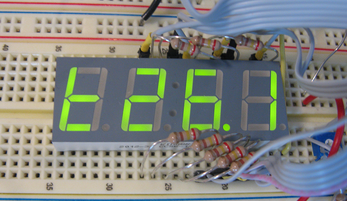 |
| Measured value is displayed on СС56-12GWA |
  ADMUX = 0b01000111; // ref voltage - Vcc, input ADC7, right-edged result
  ADCSRA = 0b10000111; // 1/128 prescaler, ADC enabled

  while(1)  {
    temperature_table_entry_type summ = 0;
    for (uint8_t i = 0; i < 64; i++) {
      ADCSRA |= _BV(ADSC);
      loop_until_bit_is_clear(ADCSRA, ADSC);
      summ += ADC;
    }
    int16_t t = calc_temperature(summ);
    ledind_num(t, 1, 0b01010011); // Output value with t-styled prefix
    _delay_ms(250);
  }
5 ms; mod: Mon, 13 Oct 2025 08:18:34 GMT; gen: Mon, 13 Jul 2026 07:06:10 GMT